
DonCorson
[AHCI]
3358

Approaching Resonance – part 2
Approaching Resonance – part 2
Don Corson, November 2013
In the first article of this series discussing resonance in watches I set up a simulation of an oscillator such as the balance wheel / hairspring pair in a mechanical watch. I was able to determine the basic parameters of the simulation so that it gives results such as I would expect for simple tests.
If you have not read my first article, it is available here.
As you have seen I finished up the last article with an oscillator excited to resonance by an external sinus wave source. Now is the time to create the system of a resonant watch, which comprises:
- Two separate oscillators
- A means of coupling between the two oscillators to be able to transfer energy between them.
A schematic view of the system looks like this: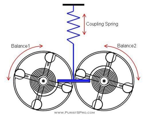
Figure 1
In my simulation the components move only as shown by the arrows, the balance wheels have only rotational movement and the coupling between the ends of the hair springs moves only vertically.
As we can see, the force at any instant on the coupling bar is equal to the force of the two hairsprings added together. The amount the coupling bar moves then depends on the spring constant of the coupling spring. A reasonable value for that spring constant is one of the first things I need to determine. I start out with a value for the coupling spring constant that corresponds to a maximum movement of the coupling spring of about 0.4mm.
For a first test with the configuration in Figure 1 I excite the balance 1 with enough impulse to achieve an amplitude of about 280° for that balance alone. Adding the coupling to the balance 2 reduces the amplitude of balance 1 to about 200°. The balance 2, which is without excitation, oscillates at about 165° just through the coupling to balance 1. This is the case that is technically called resonance. The energy of one powered oscillator is coupled to a second oscillator that is not powered. (You all know the classic example of the opera singer quietly testing the natural frequency of a wine glass so she will know which note to sing to make the glass resonate and maybe break. The singer is the powered oscillator, the glass the non-powered oscillator. The air in the room is the coupling spring.)
Let’s see if the coupled system has the frequency behaviour that we expect. I can change the inertia of the balance wheel 1 to change the natural frequency of its oscillation. I then run the simulation to see how the balance 2 reacts. In all these simulations balance 2 is set to have a natural frequency of 4Hz. The curves can be seen in Figure 2, the vertical axis is the amplitude, the horizontal axis the time in seconds. Each curve shows the evolution of the amplitude of the balance 2 (the resonating balance) with the balance 1 swinging at a certain frequency.

Figure 2
The end amplitude of balance 2 plotted over the frequency of balance 1 is seen in Figure 3. The plot looks a little crippled, but does show typical resonant frequency behaviour. The vertical axis is again the amplitude, the horizontal axis the frequency. Note that the frequency change is the result of changing the inertia of the balance wheel 1 in the simulation, just as it would be in a test of the real watch.

Figure 3
We have now seen that the coupled oscillator system shows typical resonant behaviour. Now it is time to optimise the coupling factor between balance 1 and balance 2. To do this I have run the simulation above with several coupling factors and plotted them together. The results are seen in Figure 4. Again we have the frequency of balance 1 on the horizontal axis and the amplitude of balance 2 on the vertical axis.

Figure 4
Here we can see that at high coupling factors the resonant peak becomes wider. At low coupling factors the amplitude diminishes. I will choose a coupling factor of around 133 for my further investigations.
One of the first notions that I had about resonant systems that has proved wrong is that less energy is needed to make a resonant system oscillate. After thinking about it for a while this becomes easy to understand. The amount of friction affecting the two balances is not changed by resonance so the energy dissipated during each cycle of both oscillators remains the same. This energy needs to be replaced to keep the oscillators in a steady state, whether it is in resonance or not. What does change, however, is the ability to transfer the energy between the two oscillators. We can see this below in figure 5.

Figure 5
The upper group of curves is that of balance 1 which is excited with an impulse like it would be in a watch escapement. The lower group the curves is that of balance 2 which is not excited at all, its only energy is coming through the coupling to balance 1.
For balance 1, which is supplying the energy to balance 2 through the coupling element, the curve with the lowest amplitude corresponds to a 4Hz oscillation. For balance 2 the 4Hz curve is the highest. This is the case where the most energy is transferred from balance 1 to balance 2, subtracting that energy from balance 1 and adding it to balance 2. Correspondingly, balance 1 has the highest amplitude when it is coupling the least energy to balance 2 when the frequency is far from 4Hz, either faster or slower.
Now it is time to put both balances under power as they will be in a watch with the coupling factor determined above and see how they respond. What do I see?
- The first thing I see is that, yes, both oscillators need to be exited as if they were alone as I discussed above. There is no saving of energy.
- When the natural frequencies of the oscillators are close enough so they can transfer a certain amount of energy, they enter resonance, the balances will over time synchronise and then have a small constant phase difference.
We can see this synchronisation happening in the Figure 6 below.

Figure 6
In this diagram we see the amplitude of the two balances in blue and green. In red we find the phase difference between the balances. In this case the balances started with a phase difference of -45°. We can see that there is a transfer of energy between the two balances in their changing amplitudes and that the system synchronises to a phase difference of 0° after about one minute.
In my next report I will investigate the behaviour of such a coupled oscillator system, which always tries to synchronise to a certain phase difference, compared to a system of two independent oscillators.
The production of a resonant watch has also begun, first metal has been cut. But real production will take longer than making simulations. Real testing to confirm these results will come… in time.

Approaching Resonance – part 2
Amazing project, fantastic post, eager to see what will follow.


A.L.Breguet resonance experiments